
Wimbler Flasher
Programming and test system for assembled PCBs
Programs microcontrollers, EEPROMs and flash memory, tests and calibrates your boards – and logs every step with serial number, date and operator.
from € 1,060 plus VAT
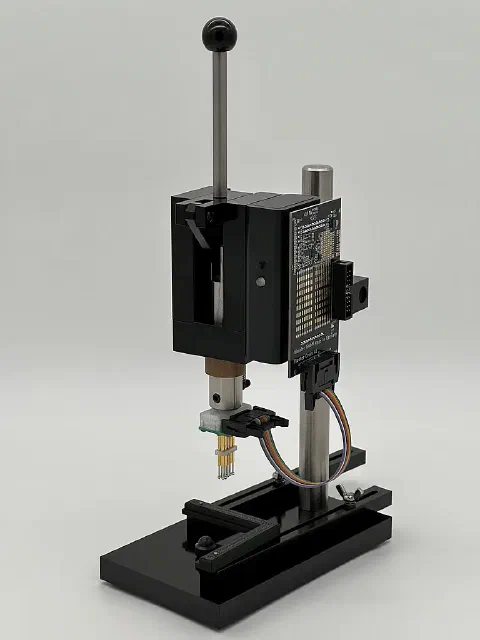
What the Flasher does
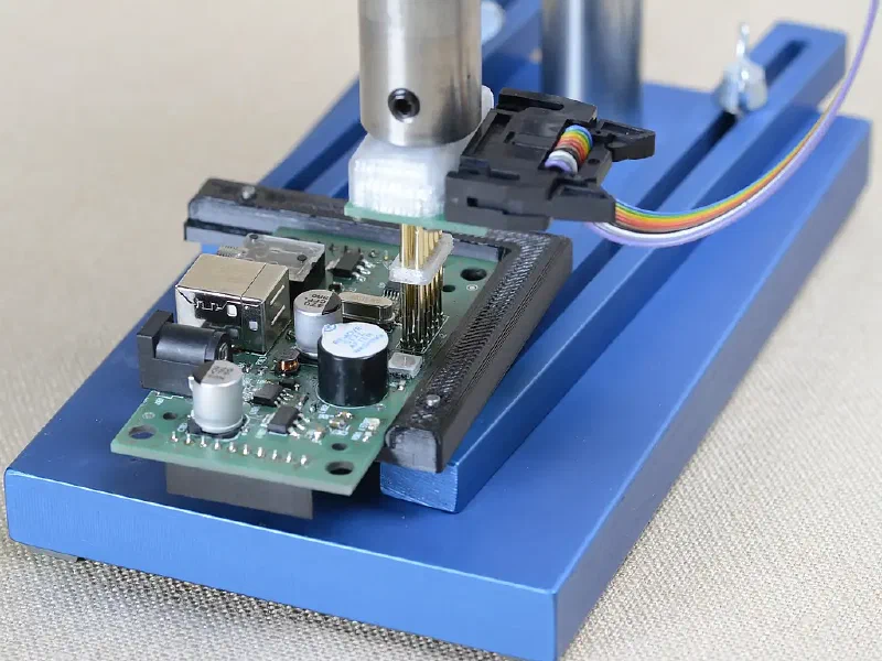
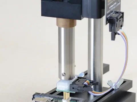
The Wimbler Flasher is a hardware and software system that connects instantly to an assembled PCB during production: it programs microcontrollers, EEPROMs and flash memory, runs functional tests and parameterizes or calibrates your boards.
The Flasher works with the programmer you already use. You automate serial programming and testing, shorten cycle times significantly and avoid operator errors.
As soon as the board is clamped, the PC software starts the sequencer – a series of steps, each performing one operation: for example erasing the microcontroller, flashing the bootloader, flashing the firmware, setting the fuses, calibrating the input circuits, testing the function and printing the label. The logger stores the result of each step in the database together with the date, the board’s serial number and the operator, and exports the data in a format ready for further processing.
Advantages
- No connector needed on the PCB – simple contact pads are enough. This saves production costs and reduces the failure rate.
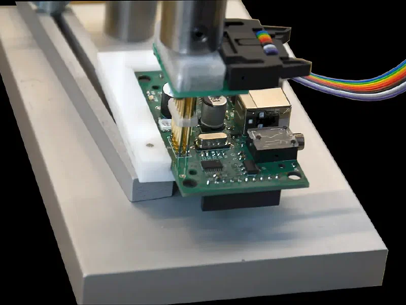
- Contact pads anywhere on the board: we build matching fixtures on request, or you print them yourself on a 3D printer.
- Flexible for different board sizes – ideal if you produce many different assemblies.
- Automation of manual work with automatic error detection and user roles with different permissions.
- Complete logging: board information is stored in the database automatically.
- Clear feedback: the result is shown by a tri-color LED and a sound signal.
- No separate power supply for the board: the Flasher supplies the target board with 5 V or 3.3 V, other voltages on request.
- 4 digital inputs and 4 digital outputs, freely assignable, plus an area for your own prototype circuits.
- Interchangeable cross-boards for different projects.
Adapters
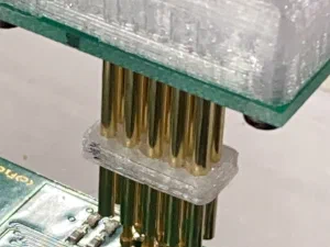
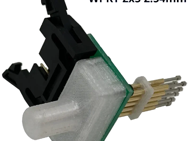
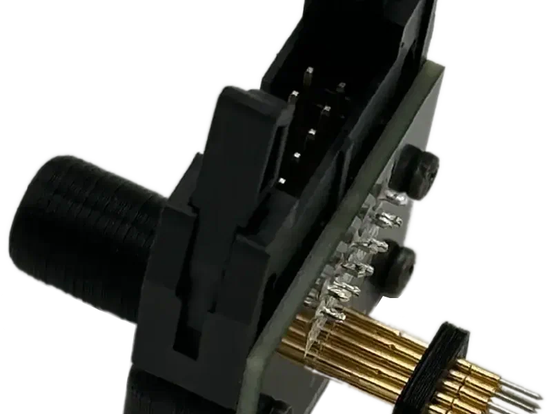
Two adapters are currently available: WPKT 2×5 with 2.54 mm and WPKT 2×5 with 1.27 mm pitch. Each adapter has 10 spring-loaded pins. Individual pins can be removed if fewer pads need to be contacted. Custom adapters are available on request.
Electronics
The Flasher electronics communicate with the PC software via USB and handle:
- starting the sequencer automatically when the press handle is lowered,
- reading the “Confirm” button – so the sequencer can pause for manual actions on the board,
- reading four inputs and switching four outputs on the cross-board,
- a sound signal at the end of programming, with different tones for success and failure,
- the tri-color LED for operating mode and OK/NOK status,
- powering the cross-board and galvanically isolating its inputs and outputs from USB.
Cross-board
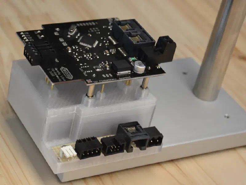
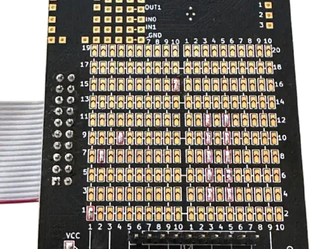
The cross-board connects any pin of the 10-pin connector (to the adapter) to any pin of the 20-pin connector (to your programmer). Each pin of the 10-pin connector can also be supplied with 3.3 V or 5 V (selected by a solder bridge), continuous current up to 1.5 A. The voltage of the external power supply (12–24 V) can also be routed to any adapter pin.
A small prototyping area lets you add your own SMD circuits – for example LEDs and buttons that the sequencer switches or reads in each step.
Example: an SWD programming port needs a 5 V supply. The “5V” solder bridge is set (default is 3.3 V) and the pins are connected as follows:
| 10-pin connector (adapter) | 20-pin connector (programmer) |
|---|---|
| 1 – VCC | 1 |
| 2 – SWDIO | 7 |
| 3 – GND | 4, 6, 8, 10, 12 |
| 4 – SWDCLK | 9 |
| 5 – GND | 4, 6, 8, 10, 12 |
| 10 – RESET | 15 |
Specifications
| Component / feature | Value |
|---|---|
| Flasher clamp | |
| Dimensions | 260 × 170 × 100 mm |
| Net weight | 2460 g |
| Working stroke | 45 mm |
| Materials | anodized aluminum, stainless steel, bronze, plastic |
| Flasher adapter | |
| Dimensions | 60 × 45 × 32 mm |
| Shank | Ø 10 mm, length 15 mm |
| Contact pins | 10 |
| Pitch | 2.54 mm or 1.27 mm (depending on adapter) |
| Flasher electronics | |
| Housing | polycarbonate, 98 × 48 × 24 mm |
| Power supply | 12–24 V, from 0.5 W |
| Interface | USB |
| Connectors | two connectors for the cross-board |
| Controls and indicators | user button, tri-color LED, sound signal |
| Cross-board | |
| Dimensions | 116 × 55 × 18 mm |
| Connectors | 2 plugs to the electronics, 10-pin to the adapter, 20-pin to the programmer |
| Inputs / outputs | 4 each, 3.3 V |
| Target board supply | 3.3 V or 5 V and 12–24 V directly from the power supply |
| Power supply unit | |
| Input | 100–240 V, 50–60 Hz |
| Output | 24 V, at least 10 W (15 W recommended) |
What our customers say
We are a company specialising in the development of a new gas system, unique worldwide, for which we developed both the hydraulic and the electronic components from scratch. Countless development steps had to be brought to market quickly and consistently in small and medium production runs, which required a continuous process of software and hardware development. We therefore needed a system that is easy to handle yet fast and reliable for loading the different software versions onto our electronic hardware – in a very simple process that warehouse staff can complete with hardly any errors. That is why we chose the Wimbler system, and we have been very satisfied with it for several years now.
Changed software is set up in a matter of seconds, and warehouse staff can load the new version onto the electronics without any interruption.
Looking back, I cannot imagine how this process could have been run reliably without the Wimbler.
Tell us about your project
A few sentences are enough. We will get back to you shortly.
Prefer to talk?
- +49 911 93111527
- [email protected]
- Königstr. 133, 90762 Fürth, Germany
Thank you!
Your enquiry has arrived. We will get back to you shortly.